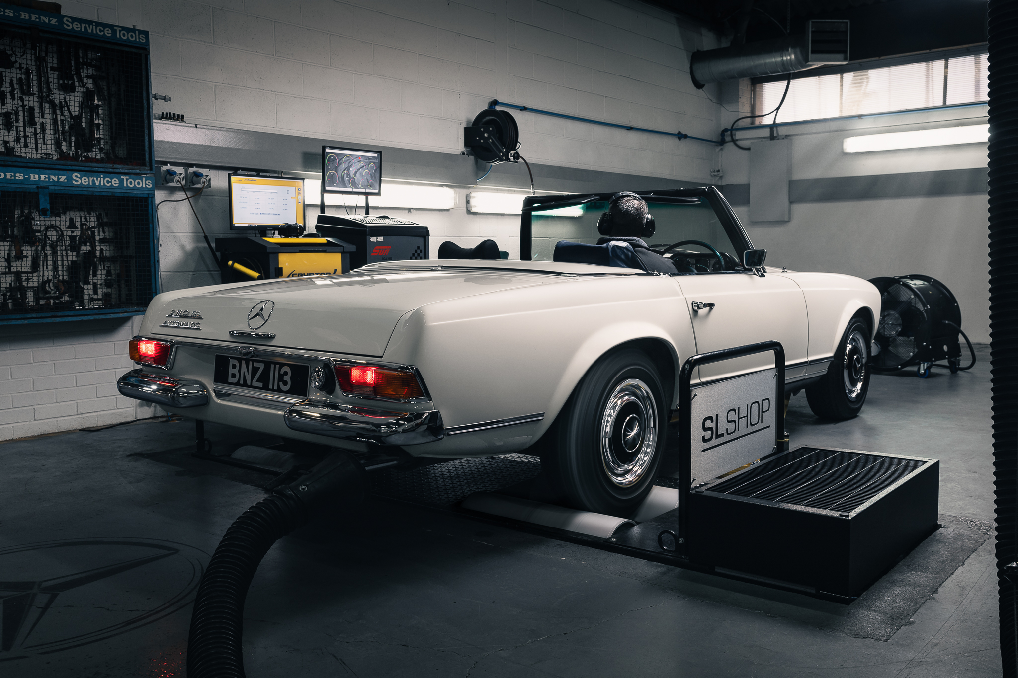
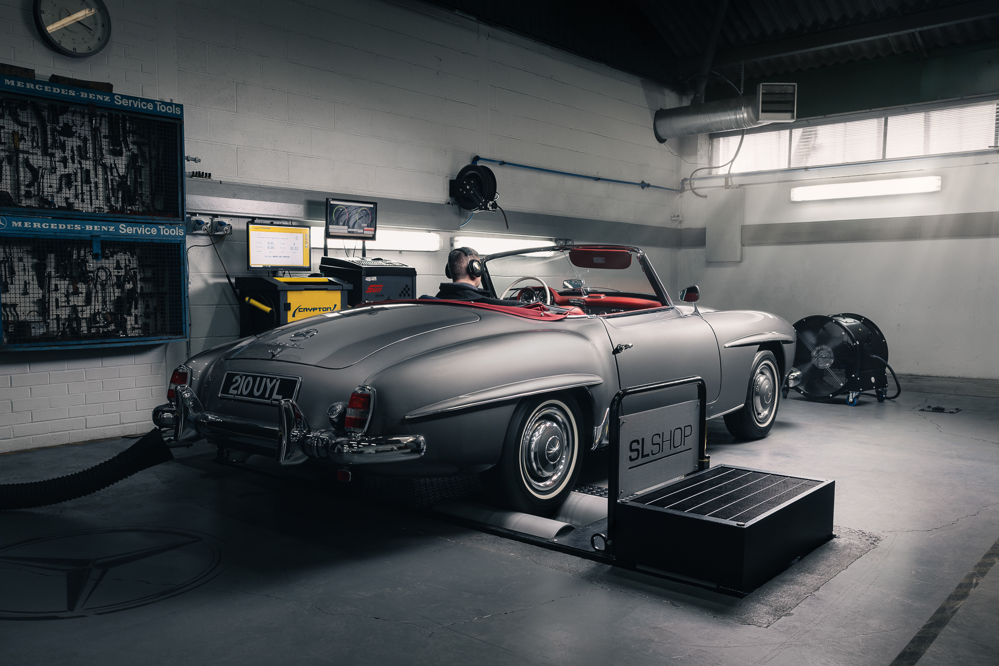
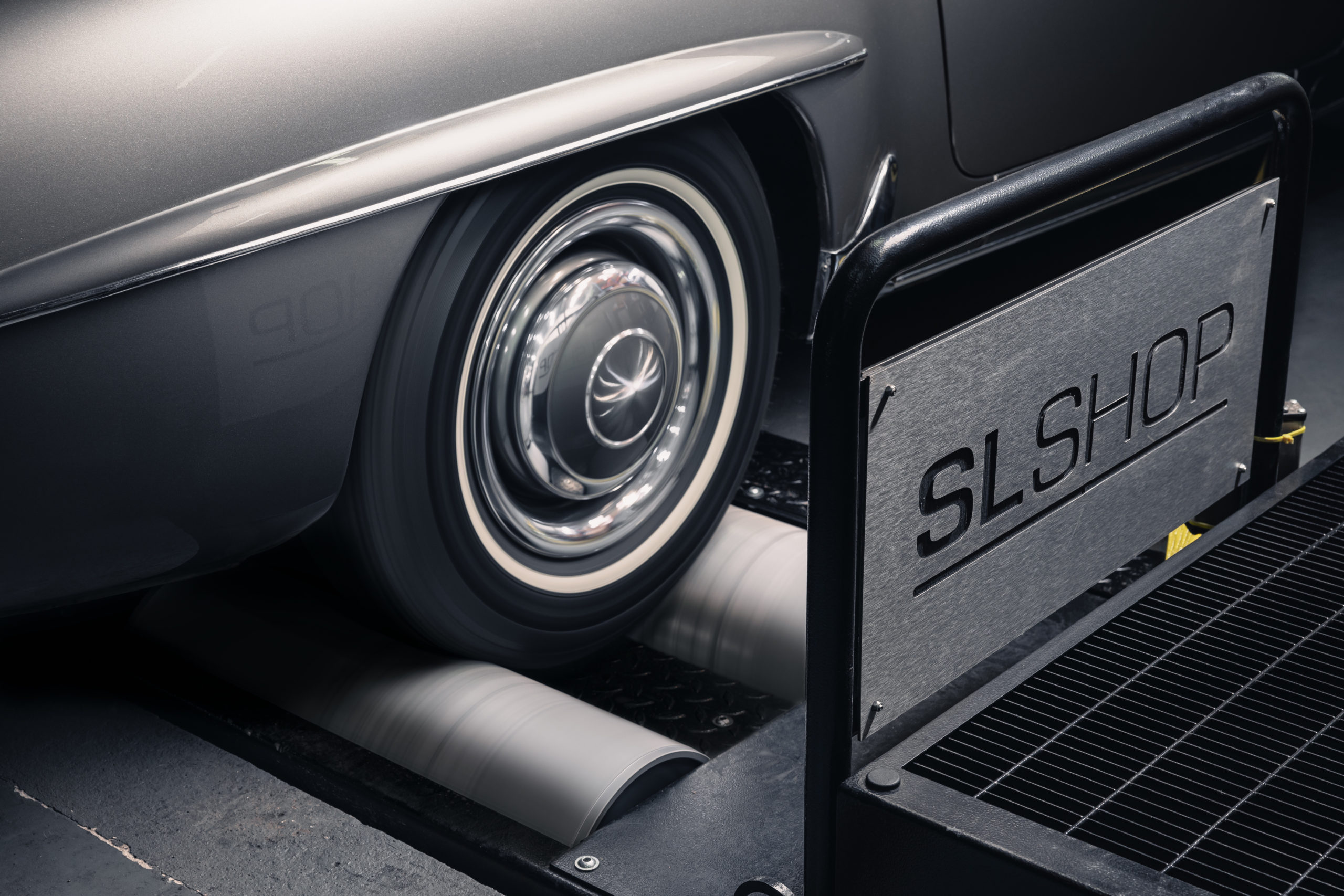
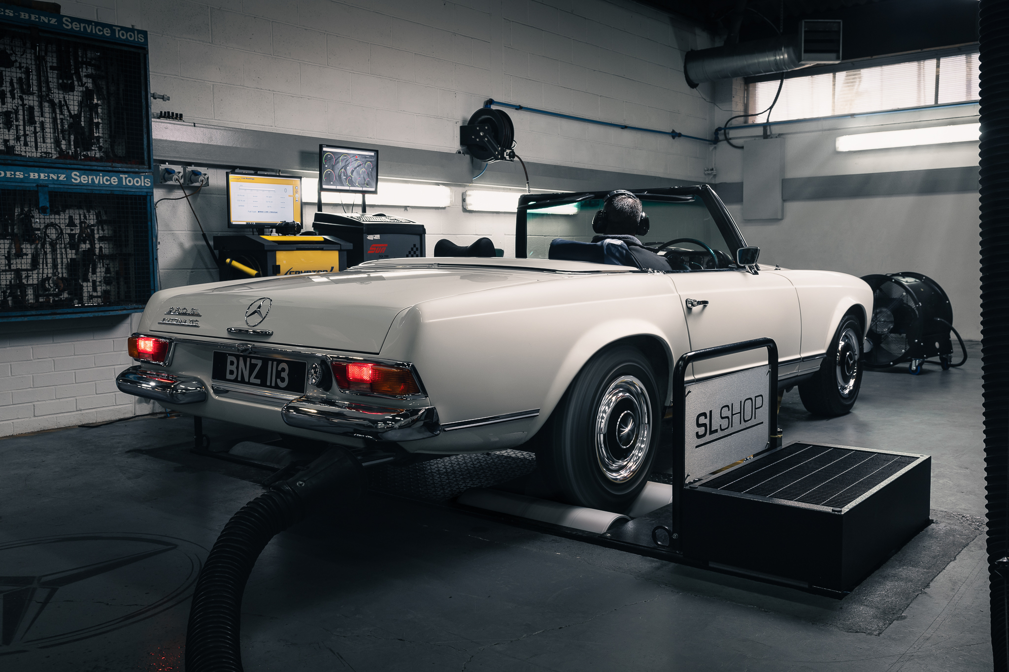
We have all felt that momentary hesitation from our car when we accelerate; we have experienced higher than normal fuel consumption under certain driving conditions and we have all felt a “misfire under load” from the engine. The reasons for these common issues can be extremely elusive to pinpoint from a workshop technician’s perspective. A Dyno allows real time simulation of on-road driving conditions allowing accurate and repeatable measurements to be taken and immediate recognition of improvements after “adjustments”.
We are the only dedicated Mercedes specialist to provide this service inhouse.
Within the age range of classic Mercedes vehicles from 1950 to the 1990’s which are our focus at SLSHOP, we encounter a wide range of technology spanning four decades. Our technicians have to be competent in all aspects of the various systems found on classic Mercedes vehicles: Carburation; Mechanical Fuel Injection; Early Air Flow Injection technology and more up to date, Electronic Fuel Injection (EFI).
What can you, the customer, expect from a correctly set up and tuned vehicle?
– Primarily a better driving experience. It is not always about more power, in fact we have often seen vehicles that have been “tuned” at motorsports companies that are extremely unpleasant to drive on the road. Our focus will always be on drivability so you will enjoy your car to its maximum.
– In a before and after set up comparison, you may notice one or more of the following: a smoother power delivery; better acceleration; improved fuel economy; lower operating temperatures; better starting; smoother idle; the list can go on but the one thing we come back to is a better driving experience.
How will we use this service?
– It will be part of our diagnostic procedure for engine performance issues.
– It will be offered as a stand-alone engine check and set up.
– It will be offered as an experience day – where you can bring your vehicle and watch, real time, as measurements are taken and key indicators such as power and torque curves are plotted and printed whilst also having the opportunity to discuss with the technician carrying out the diagnosis, in real time.
Book your car in here.
Let’s get more technical
Since the internal combustion engine was invented, the motor industry has been striving to develop ever more efficient ways of solving the problem of getting the correct amount of fuel into the cylinders under all conditions.
What is the correct amount of fuel, I hear you asking. Well, for pump Petrol/Gasoline to burn completely, the ratio of fuel to air (the stoichiometric ratio) is 14.7 to 1 by weight.
To put that into context, air has density of 1.204 kg/m3 at “normal” atmospheric temperature and pressure. So, to provide enough petrol to completely combust 1 cubic meter of air we must provide 82 grams of fuel or 0.106 litres of fuel.
If we consider our 500 SL with its 5.0 litre engine idling at, say, 1000 rpm then every minute, if it was not controlled by restricting the intake system with the throttle, it would consume 2500 litres of air and need 0.265 litres of fuel. If we consider it now running on wide open throttle at 5000 rpm, it would need 1.325 litres of fuel per minute or 79.5 litres per hour.
We can appreciate how important it is to accurately control fuel delivery under differing conditions to maintain the correct Air Fuel Ratio.
The role of technology
Today we are experiencing the most advanced development in engine design, largely driven by the need to improve efficiency and reduce fuel consumption and so-called greenhouse gas emissions.
Universally the fuelling of today’s ICE power plants is electronically controlled EFI.
So, how does it work? Let’s draw a comparison with the humble kitchen tap. When you turn on the tap, the longer it is open, the more water flows through and we all know that is affected by the “Mains Pressure” – if the pressure is lower, the flow rate is less. Obviously, the size of the tap plays an important part. So, what have we just confirmed with this simple analogy? There are three factors to consider:
- Time: Length of time the tap is open.
- Pressure: Pressure forcing the water out.
- Orifice: Size of the tap.
It is precisely these factors that Modern EFI systems control and are, effectively, based on the principles of Fluid Dynamics. When calculating the calibration values for any given engine, two of the three above are considered constant in any given design.
– The Fuel Pressure is usually controlled by a mechanical fuel pressure regulator; typically fuel pressure is set between 3 and 4.5 bar.
– The Fuel Injector “Orifice” size is a function of the design and cannot be varied in normal operation of the engine.
– So that leaves us with TIME as the variable and provides the changes in fuel delivery we need.
Modern electronic injectors can be opened and closed in milliseconds, and it is with that we can refine our fuel delivery quantities when the opening times are controlled by a modern microprocessor driven ECU.
The role of the ECU
The ECU must be able to receive information about the real time conditions under which the engine is operating and then perform multiple calculations to establish the correct injector opening duration for optimum fuelling.
Typically those inputs relate to:-
- Engine coolant temperature.
- Ambient/intake air temperature.
- Throttle position.
- Load on engine.
- Crankshaft position.
- Camshaft position (sequential injection applications).
- Engine speed RPM.
- Exhaust gas composition (closed loop systems).
- Knock Sensor- detects over advanced ignition timing.
This information is transmitted to the ECU as electrical signals from a series of “engine sensors”. Before any measurements are taken on the rolling road, it is important to be confident that all sensors are operating within tolerances.
We often hear the term ‘re-mapped”. What does it mean? Well, effectively, it is changing the manufacturer’s calibration of both fuel delivery and injection timing. “Re-mapping” requires software that can interact with the ECU and make adjustments to the original calibration or “map”.
It is a skilled operation and requires an in-depth knowledge of the various parameters contained within the calibration process. A skilled operative is able to “tailor” a map to deliver differing driving characteristics dependant on the purpose for which the vehicle is intended.
To a degree, we have started at the end of the journey with a summary of the latest fuel control technology; next, we will look back into an era before electronics and the art of carburettor tuning.
The humble carburettor
Where does the name, “carburettor“, come from? It is derived from the French verb “carburet” which means to combine with Carbon, or in in this case, to enrich a gas (air-being a combination of gases) by combining it with Carbon or Hydrocarbons such as petrol.
The development of the carburettor is a classic example of how different engineers have found different ways of solving the same problem. There are many brands that you may have encountered. Names like Solex, Zenith, Webber, Holley, Dellorto, SU, Stromberg, Amal are probably the most widely recognised.
Carburettor design follows two differing routes: either fixed jet or variable jet design. Additionally, the physical design can vary such as down draught; side draught; single barrel; multiple barrel; etc.
Now, to take you back to the three factors we identified earlier in our kitchen tap analogy and update them with reference to the carburettor.
- Time – The length of time the tap is open – in a carburettor there is effectively no tap so time can be considered to be a constant.
- Pressure – The pressure forcing the water out – within the operation of the carburettor we must look at pressure differentials rather than specific pressure and the way that increasing or decreasing the pressure differential across certain areas is used to vary fuel delivery.
- Orifice – The size of the tap – we have previously mentioned the word “jet”, and this effectively sets the orifice that the fuel can flow through.
At SLSHOP we encounter carburettors in our Heritage range of vehicle typically from the 1950’s era and most commonly the 190SL models that were fitted with twin side draught Solex carburettors of a fixed jet design. Many of these cars have been modified to replace the Solex items with Weber units of similar design.
Carburettor “tuning” is a very skilled job and has over the years been attempted by many and mastered by few. Those that joined the elite group of people who ‘can’ were widely sought after and valued by performance car enthusiasts and manufacturers alike.
Today at SLSHOP, we are fortunate to have the rolling road facility and the benefit of advanced gas analysers which enable the tuning process to become more of a precise science than a ‘black art’. Additionally, we have built up a stock of the various components that are needed to make fuelling adjustments enabling efficient and speedy changes with instantly measurable results. Not least, we also have the knowledge based on experience with specific models.
Unlike the modern EFI system we looked at earlier, the carburettor does not have the ability to respond to the multitude of variables to constantly maintain the ideal AFR of 14.7 to 1 typically, a carburettor will work in the range of between 12 and 18 to one AFR- where 12 is a rich mixture and 18 is a weak or lean mixture.
When setting up an engine running with carburettor’s we look at three main areas:
- Idle mixture and performance;
- Part load or part throttle at mid-range RPM; and
- Full load and throttle openings at high range RPM
We monitor the AFR under those basic conditions. We also perform maximum power test which provides us with a graph giving a visual representation of both the power curve and torque curve the engine is delivering, all of which is being done before any adjustments are made to establish our base line.
So, to go back to our three factors of Time/Pressure/Orifice, when trying to understand the function of the carburettor, the most difficult concept is differential pressure. What is it and how do we control it?
Here, we want to stress that an engine does not “suck” fuel into itself so you must eliminate that myth from your mind. Air enters the engine due to low pressure, created within the inlet manifold by the downward stroke of the piston on the induction cycle.
At this stage, we must introduce the concept of the Venturi and Bernoulli principle. This basic principle dates back to 1738 when it was discovered that with an increase in the speed of a fluid (and in our case, air can be considered to be a fluid) the pressure within that fluid decreases. The Venturi plays an important role here as it reduces the size of the bore that the air must pass through to enter the engine so, for any given volume of air, the rate of flow or speed will increase and the pressure will drop so we are able to use varying sizes of Venturis commonly referred to as ‘chokes’ to increase or decrease the air flow speed and subsequently vary the pressure differential within the carburettor, compared to atmospheric pressure.
As an example, we know that the bore of the Solex 44PHH carburettor fitted to the 190SL is 44mm but these are actually “choked down to between 36 and 32 mm. This is for the purpose of increasing both the speed of the air entering the engine and the pressure differential across the carburettor.
We know that air at a higher pressure will always move towards air at a lower pressure and it is this movement of air through the carburettor chambers that allows the mixing of the fuel with the air to form a combustible emulsion which is ignited by a spark once compressed within the cylinders. We can also use the jet size to tune the carburettor and it is this ability to vary the jet sizes (by physically changing the jets) and vary the pressure differentials that enable us to control the AFR with a carburettor. For the moment that’s all we want to say about Carburettors or we will get into too much detail which is outside the scope of this article. However, hopefully the above has given an insight into the skills required and the role a rolling road can play in setting up your car for best performance and efficiency.
Early Petrol Injection
Bosch were leaders in diesel engine fuel injection and so it was inevitable that they should develop a petrol injection system that had many physical and operational similarities. For the W113 Pagoda range, Mercedes chose Bosch to develop a petrol fuel injection system. This system is a purely mechanical system and utilises an inline fuel injection pump that has individual elements for each cylinder of the engine. It was known as an MFI system -Mechanical Fuel Injection.
Fuel was delivered to this pump at relatively low pressure and the high pressure necessary for atomisation of the fuel was developed by the stroke of the individual elements within the pump. Calibration was achieved by varying the amount fuel entering the individual elements within the fuel pump which would then be forced by pressure through individual nozzles positioned within the inlet air tracts of the manifold before entering the cylinders.
There were basic provisions to compensate for engine temperature and atmospheric pressure and basic enrichment for cold starting the calibration, was directly linked to the throttle position. The installation of the pump had to be “timed” with the engine and in a similar way, a distributor had to be installed. On-car adjustments were limited and the system was complicated and expensive to maintain.
Today at SLSHOP, we have our own in-house strip and rebuild/calibration facilities for these pumps and coupled with the rolling road facility and an expert knowledge base, we believe we are best placed in the market to diagnose and repair any issues with this MFI system. As part of our W113 Pagoda rolling road experience day, we include a tour of our rebuild operation.
Technology moved fast and by the time the R107 product range was launched, the MFI system had run its course and we were into a new era of AFI Systems that would continue until the 1990s, in various guises.
Bosch AFI
Throughout the period from 1972 to 1990, evolution was the key word. Advances in technology and changing legislation, as well as greater demand for fuel efficiency, fuelled the fires of development. During that period, the R107 product saw three major changes to the AFI system in Europe and a unique variant for the US market.
Ironically the first variant – D Jetronic was not dissimilar to the EFI systems we have today -the injectors were controlled electronically (as in today’s EFI) but the control system technology was poor with limited computing power contained within the ECU. The main control parameter was the Manifold Absolute Pressure (MAP). The sensor providing this information was expensive to produce and unreliable too and in service, difficult to diagnose as faulty. In-car maintenance and adjustments were limited to checking sensor operations, throttle position settings and continuity of wiring.
By 1975, the D Jetronic had been superseded by K Jetronic. K for Continuous – this was the first time we saw an air flow meter, effectively a device to measure the volume of air entering the inlet manifold of the engine. Obvious, you might think, considering we want to calculate the fuel requirement in proportion to the volume of air. However, initially it was not used for that purpose but to provide a mechanical leverage onto a piston that would control the fuel delivery within the metering unit.
We are, to a degree getting ahead of ourselves. Continuous meant that fuel under pressure was constantly supplied to the fuel injectors which were a simple nozzle with a valve which required pressure to be opened. Once the engine was running, it was continuously injecting fuel and the amount of fuel delivered was in direct relationship with the movement of the air flow meter controlled by the movement of a piston in the metering unit. Fuel was supplied to the metering unit by a high-pressure pump. There was a degree of electronics involved, especially in the area of idle speed control but no ECU controlled the fuel delivery.
So how does this system corollate with our kitchen tap analogy and the three controlling factors of Time/Pressure/Orifice?
- Time – The length of time the tap is open – this is a continuous injection system so the tap can be considered to always be open provided there is sufficient system pressure.
- Pressure – The pressure forcing the water out – here we have to distinguish between two pressure systems – firstly to open the injectors we need a basic pressure which remains constant irrespective of fuel volume. Secondly, we need a differential pressure that compensates for variations in fuel flow volumes.
- Orifice – The size of the tap – the injector orifice is fixed by design and can be considered constant. However within the metering unit the calibration is achieved by varying the cross-sectional area that the fuel must pass through to reach the injectors.
When carrying out system checks on the rolling road, we are looking for variations in fuel pressure in different parts of the system; comparing the results with manufacturers’ specifications as well as checking sensor operation and throttle plate signals and primarily monitoring exhaust gas composition. This is an open loop system where the exhaust gas composition is not taken into account in the calibration.
Eventually a new system called KE Jetronic was introduced. Driven by the need for greater control over emissions and the promise of improved fuel economy, a degree of electronic control was introduced. Outwardly similar to its predecessor there were very few interchangeable parts. Fuel is delivered in the same way as the previous system; the difference is that the fuel system pressure is now not controlled by a mechanical pressure relief valve but by an electronic actuator that is controlled by an ECU. This provides greater accuracy and faster response to changing conditions.
Rolling road procedures are identical to the earlier system. KE Jetronic can be operated in both an open loop and a closed loop configuration by the addition of a lambda sensor as found in early R129 models. Our technicians are familiar with both K Jet and KE systems enabling accurate and efficient diagnostic results.
We must make a final mention of a system that was developed for the US market prior to the introduction of the KE variant. We call it K Lambda and we see it on cars that come from the US. It is not the same as a closed loop KE system but more of a modified K Jet system operating on a closed loop basis with lambda sensor control. Not much information is available and being specific for the US market, we find it is very sensitive to modern fuel compositions and additionally, parts’ identification and supply are difficult.
So now we are back at the beginning and the development timeline is at the EFI threshold.
So what about the future?
Here at SLSHOP, we are constantly aware of the need for change and the ever-higher expectations of our customers based on the driving experience that their everyday car delivers. We have been working on solutions to future proof the classic SL range. Under our SportLine brand of products, we are now able to offer a full EFI and engine management conversion for your classic R107. Results have shown improved driveability, improved fuel consumption and improved reliability with resulting lower maintenance costs. Customer feedback on converted cars has been extremely positive.
We hope you have found this interesting and gained a better understanding and appreciation of what is involved in maintaining, tuning and diagnosis of the different types of fuel systems within the classic Mercedes range.
We have all felt that momentary hesitation from our car when we accelerate; we have experienced higher than normal fuel consumption under certain driving conditions and we have all felt a “misfire under load” from the engine. The reasons for these common issues can be extremely elusive to pinpoint from a workshop technician’s perspective. A Dyno allows real time simulation of on-road driving conditions allowing accurate and repeatable measurements to be taken and immediate recognition of improvements after “adjustments”.
We are the only dedicated Mercedes specialist to provide this service inhouse.
Within the age range of classic Mercedes vehicles from 1950 to the 1990’s which are our focus at SLSHOP, we encounter a wide range of technology spanning four decades. Our technicians have to be competent in all aspects of the various systems found on classic Mercedes vehicles: Carburation; Mechanical Fuel Injection; Early Air Flow Injection technology and more up to date, Electronic Fuel Injection (EFI).

What can you, the customer, expect from a correctly set up and tuned vehicle?
– Primarily a better driving experience. It is not always about more power, in fact we have often seen vehicles that have been “tuned” at motorsports companies that are extremely unpleasant to drive on the road. Our focus will always be on drivability so you will enjoy your car to its maximum.
– In a before and after set up comparison, you may notice one or more of the following: a smoother power delivery; better acceleration; improved fuel economy; lower operating temperatures; better starting; smoother idle; the list can go on but the one thing we come back to is a better driving experience.
How will we use this service?
– It will be part of our diagnostic procedure for engine performance issues.
– It will be offered as a stand-alone engine check and set up.
– It will be offered as an experience day – where you can bring your vehicle and watch, real time, as measurements are taken and key indicators such as power and torque curves are plotted and printed whilst also having the opportunity to discuss with the technician carrying out the diagnosis, in real time.
Book your car in here.
Let’s get more technical
Since the internal combustion engine was invented, the motor industry has been striving to develop ever more efficient ways of solving the problem of getting the correct amount of fuel into the cylinders under all conditions.
What is the correct amount of fuel, I hear you asking. Well, for pump Petrol/Gasoline to burn completely, the ratio of fuel to air (the stoichiometric ratio) is 14.7 to 1 by weight.
To put that into context, air has density of 1.204 kg/m3 at “normal” atmospheric temperature and pressure. So, to provide enough petrol to completely combust 1 cubic meter of air we must provide 82 grams of fuel or 0.106 litres of fuel.
If we consider our 500 SL with its 5.0 litre engine idling at, say, 1000 rpm then every minute, if it was not controlled by restricting the intake system with the throttle, it would consume 2500 litres of air and need 0.265 litres of fuel. If we consider it now running on wide open throttle at 5000 rpm, it would need 1.325 litres of fuel per minute or 79.5 litres per hour.
We can appreciate how important it is to accurately control fuel delivery under differing conditions to maintain the correct Air Fuel Ratio.
The role of technology
Today we are experiencing the most advanced development in engine design, largely driven by the need to improve efficiency and reduce fuel consumption and so-called greenhouse gas emissions.
Universally the fuelling of today’s ICE power plants is electronically controlled EFI.
So, how does it work? Let’s draw a comparison with the humble kitchen tap. When you turn on the tap, the longer it is open, the more water flows through and we all know that is affected by the “Mains Pressure” – if the pressure is lower, the flow rate is less. Obviously, the size of the tap plays an important part. So, what have we just confirmed with this simple analogy? There are three factors to consider:
- Time: Length of time the tap is open.
- Pressure: Pressure forcing the water out.
- Orifice: Size of the tap.
It is precisely these factors that Modern EFI systems control and are, effectively, based on the principles of Fluid Dynamics. When calculating the calibration values for any given engine, two of the three above are considered constant in any given design.
– The Fuel Pressure is usually controlled by a mechanical fuel pressure regulator; typically fuel pressure is set between 3 and 4.5 bar.
– The Fuel Injector “Orifice” size is a function of the design and cannot be varied in normal operation of the engine.
– So that leaves us with TIME as the variable and provides the changes in fuel delivery we need.
Modern electronic injectors can be opened and closed in milliseconds, and it is with that we can refine our fuel delivery quantities when the opening times are controlled by a modern microprocessor driven ECU.
The role of the ECU
The ECU must be able to receive information about the real time conditions under which the engine is operating and then perform multiple calculations to establish the correct injector opening duration for optimum fuelling.
Typically those inputs relate to:-
- Engine coolant temperature.
- Ambient/intake air temperature.
- Throttle position.
- Load on engine.
- Crankshaft position.
- Camshaft position (sequential injection applications).
- Engine speed RPM.
- Exhaust gas composition (closed loop systems).
- Knock Sensor- detects over advanced ignition timing.
This information is transmitted to the ECU as electrical signals from a series of “engine sensors”. Before any measurements are taken on the rolling road, it is important to be confident that all sensors are operating within tolerances.
We often hear the term ‘re-mapped”. What does it mean? Well, effectively, it is changing the manufacturer’s calibration of both fuel delivery and injection timing. “Re-mapping” requires software that can interact with the ECU and make adjustments to the original calibration or “map”.
It is a skilled operation and requires an in-depth knowledge of the various parameters contained within the calibration process. A skilled operative is able to “tailor” a map to deliver differing driving characteristics dependant on the purpose for which the vehicle is intended.
To a degree, we have started at the end of the journey with a summary of the latest fuel control technology; next, we will look back into an era before electronics and the art of carburettor tuning.
The humble carburettor
Where does the name, “carburettor“, come from? It is derived from the French verb “carburet” which means to combine with Carbon, or in in this case, to enrich a gas (air-being a combination of gases) by combining it with Carbon or Hydrocarbons such as petrol.
The development of the carburettor is a classic example of how different engineers have found different ways of solving the same problem. There are many brands that you may have encountered. Names like Solex, Zenith, Webber, Holley, Dellorto, SU, Stromberg, Amal are probably the most widely recognised.
Carburettor design follows two differing routes: either fixed jet or variable jet design. Additionally, the physical design can vary such as down draught; side draught; single barrel; multiple barrel; etc.
Now, to take you back to the three factors we identified earlier in our kitchen tap analogy and update them with reference to the carburettor.
- Time – The length of time the tap is open – in a carburettor there is effectively no tap so time can be considered to be a constant.
- Pressure – The pressure forcing the water out – within the operation of the carburettor we must look at pressure differentials rather than specific pressure and the way that increasing or decreasing the pressure differential across certain areas is used to vary fuel delivery.
- Orifice – The size of the tap – we have previously mentioned the word “jet”, and this effectively sets the orifice that the fuel can flow through.
At SLSHOP we encounter carburettors in our Heritage range of vehicle typically from the 1950’s era and most commonly the 190SL models that were fitted with twin side draught Solex carburettors of a fixed jet design. Many of these cars have been modified to replace the Solex items with Weber units of similar design.
Carburettor “tuning” is a very skilled job and has over the years been attempted by many and mastered by few. Those that joined the elite group of people who ‘can’ were widely sought after and valued by performance car enthusiasts and manufacturers alike.
Today at SLSHOP, we are fortunate to have the rolling road facility and the benefit of advanced gas analysers which enable the tuning process to become more of a precise science than a ‘black art’. Additionally, we have built up a stock of the various components that are needed to make fuelling adjustments enabling efficient and speedy changes with instantly measurable results. Not least, we also have the knowledge based on experience with specific models.
Unlike the modern EFI system we looked at earlier, the carburettor does not have the ability to respond to the multitude of variables to constantly maintain the ideal AFR of 14.7 to 1 typically, a carburettor will work in the range of between 12 and 18 to one AFR- where 12 is a rich mixture and 18 is a weak or lean mixture.
When setting up an engine running with carburettor’s we look at three main areas:
- Idle mixture and performance;
- Part load or part throttle at mid-range RPM; and
- Full load and throttle openings at high range RPM
We monitor the AFR under those basic conditions. We also perform maximum power test which provides us with a graph giving a visual representation of both the power curve and torque curve the engine is delivering, all of which is being done before any adjustments are made to establish our base line.
So, to go back to our three factors of Time/Pressure/Orifice, when trying to understand the function of the carburettor, the most difficult concept is differential pressure. What is it and how do we control it?
Here, we want to stress that an engine does not “suck” fuel into itself so you must eliminate that myth from your mind. Air enters the engine due to low pressure, created within the inlet manifold by the downward stroke of the piston on the induction cycle.
At this stage, we must introduce the concept of the Venturi and Bernoulli principle. This basic principle dates back to 1738 when it was discovered that with an increase in the speed of a fluid (and in our case, air can be considered to be a fluid) the pressure within that fluid decreases. The Venturi plays an important role here as it reduces the size of the bore that the air must pass through to enter the engine so, for any given volume of air, the rate of flow or speed will increase and the pressure will drop so we are able to use varying sizes of Venturis commonly referred to as ‘chokes’ to increase or decrease the air flow speed and subsequently vary the pressure differential within the carburettor, compared to atmospheric pressure.
As an example, we know that the bore of the Solex 44PHH carburettor fitted to the 190SL is 44mm but these are actually “choked down to between 36 and 32 mm. This is for the purpose of increasing both the speed of the air entering the engine and the pressure differential across the carburettor.
We know that air at a higher pressure will always move towards air at a lower pressure and it is this movement of air through the carburettor chambers that allows the mixing of the fuel with the air to form a combustible emulsion which is ignited by a spark once compressed within the cylinders. We can also use the jet size to tune the carburettor and it is this ability to vary the jet sizes (by physically changing the jets) and vary the pressure differentials that enable us to control the AFR with a carburettor. For the moment that’s all we want to say about Carburettors or we will get into too much detail which is outside the scope of this article. However, hopefully the above has given an insight into the skills required and the role a rolling road can play in setting up your car for best performance and efficiency.
Early Petrol Injection
Bosch were leaders in diesel engine fuel injection and so it was inevitable that they should develop a petrol injection system that had many physical and operational similarities. For the W113 Pagoda range, Mercedes chose Bosch to develop a petrol fuel injection system. This system is a purely mechanical system and utilises an inline fuel injection pump that has individual elements for each cylinder of the engine. It was known as an MFI system -Mechanical Fuel Injection.
Fuel was delivered to this pump at relatively low pressure and the high pressure necessary for atomisation of the fuel was developed by the stroke of the individual elements within the pump. Calibration was achieved by varying the amount fuel entering the individual elements within the fuel pump which would then be forced by pressure through individual nozzles positioned within the inlet air tracts of the manifold before entering the cylinders.
There were basic provisions to compensate for engine temperature and atmospheric pressure and basic enrichment for cold starting the calibration, was directly linked to the throttle position. The installation of the pump had to be “timed” with the engine and in a similar way, a distributor had to be installed. On-car adjustments were limited and the system was complicated and expensive to maintain.
Today at SLSHOP, we have our own in-house strip and rebuild/calibration facilities for these pumps and coupled with the rolling road facility and an expert knowledge base, we believe we are best placed in the market to diagnose and repair any issues with this MFI system. As part of our W113 Pagoda rolling road experience day, we include a tour of our rebuild operation.

Technology moved fast and by the time the R107 product range was launched, the MFI system had run its course and we were into a new era of AFI Systems that would continue until the 1990s, in various guises.
Bosch AFI
Throughout the period from 1972 to 1990, evolution was the key word. Advances in technology and changing legislation, as well as greater demand for fuel efficiency, fuelled the fires of development. During that period, the R107 product saw three major changes to the AFI system in Europe and a unique variant for the US market.
Ironically the first variant – D Jetronic was not dissimilar to the EFI systems we have today -the injectors were controlled electronically (as in today’s EFI) but the control system technology was poor with limited computing power contained within the ECU. The main control parameter was the Manifold Absolute Pressure (MAP). The sensor providing this information was expensive to produce and unreliable too and in service, difficult to diagnose as faulty. In-car maintenance and adjustments were limited to checking sensor operations, throttle position settings and continuity of wiring.
By 1975, the D Jetronic had been superseded by K Jetronic. K for Continuous – this was the first time we saw an air flow meter, effectively a device to measure the volume of air entering the inlet manifold of the engine. Obvious, you might think, considering we want to calculate the fuel requirement in proportion to the volume of air. However, initially it was not used for that purpose but to provide a mechanical leverage onto a piston that would control the fuel delivery within the metering unit.
We are, to a degree getting ahead of ourselves. Continuous meant that fuel under pressure was constantly supplied to the fuel injectors which were a simple nozzle with a valve which required pressure to be opened. Once the engine was running, it was continuously injecting fuel and the amount of fuel delivered was in direct relationship with the movement of the air flow meter controlled by the movement of a piston in the metering unit. Fuel was supplied to the metering unit by a high-pressure pump. There was a degree of electronics involved, especially in the area of idle speed control but no ECU controlled the fuel delivery.
So how does this system corollate with our kitchen tap analogy and the three controlling factors of Time/Pressure/Orifice?
- Time – The length of time the tap is open – this is a continuous injection system so the tap can be considered to always be open provided there is sufficient system pressure.
- Pressure – The pressure forcing the water out – here we have to distinguish between two pressure systems – firstly to open the injectors we need a basic pressure which remains constant irrespective of fuel volume. Secondly, we need a differential pressure that compensates for variations in fuel flow volumes.
- Orifice – The size of the tap – the injector orifice is fixed by design and can be considered constant. However within the metering unit the calibration is achieved by varying the cross-sectional area that the fuel must pass through to reach the injectors.
When carrying out system checks on the rolling road, we are looking for variations in fuel pressure in different parts of the system; comparing the results with manufacturers’ specifications as well as checking sensor operation and throttle plate signals and primarily monitoring exhaust gas composition. This is an open loop system where the exhaust gas composition is not taken into account in the calibration.
Eventually a new system called KE Jetronic was introduced. Driven by the need for greater control over emissions and the promise of improved fuel economy, a degree of electronic control was introduced. Outwardly similar to its predecessor there were very few interchangeable parts. Fuel is delivered in the same way as the previous system; the difference is that the fuel system pressure is now not controlled by a mechanical pressure relief valve but by an electronic actuator that is controlled by an ECU. This provides greater accuracy and faster response to changing conditions.
Rolling road procedures are identical to the earlier system. KE Jetronic can be operated in both an open loop and a closed loop configuration by the addition of a lambda sensor as found in early R129 models. Our technicians are familiar with both K Jet and KE systems enabling accurate and efficient diagnostic results.
We must make a final mention of a system that was developed for the US market prior to the introduction of the KE variant. We call it K Lambda and we see it on cars that come from the US. It is not the same as a closed loop KE system but more of a modified K Jet system operating on a closed loop basis with lambda sensor control. Not much information is available and being specific for the US market, we find it is very sensitive to modern fuel compositions and additionally, parts’ identification and supply are difficult.
So now we are back at the beginning and the development timeline is at the EFI threshold.

So what about the future?
Here at SLSHOP, we are constantly aware of the need for change and the ever-higher expectations of our customers based on the driving experience that their everyday car delivers. We have been working on solutions to future proof the classic SL range. Under our SportLine brand of products, we are now able to offer a full EFI and engine management conversion for your classic R107. Results have shown improved driveability, improved fuel consumption and improved reliability with resulting lower maintenance costs. Customer feedback on converted cars has been extremely positive.
We hope you have found this interesting and gained a better understanding and appreciation of what is involved in maintaining, tuning and diagnosis of the different types of fuel systems within the classic Mercedes range.
More from Journal
CARE
THE ULTIMATE CERTIFIED SERVICING INVESTMENT PLAN
Your ownership journey matters to us, which is why we have created a simple certified servicing investment plan, tailored to your individual needs and aspirations.
Start investing today and our dedicated CARE team will work with you to increase the value and enjoyment you receive from your vehicle.

STAY IN TUNE WITH SLSHOP MOMENTS
As part of SLSHOP’s community of enthusiasts, you’ll be the first to hear about events and tours, key product offers, exciting stories from owners around the world and of course… our latest additions to the showroom. So, be the first to know and you might just sneak a car on your driveway or take your car’s condition to new heights with our exclusive replacement parts.
Or, visit SLSHOP Journal
